|
Verification
Tests held and report made at the University of the German Federal Armed Forces, Munich
Translation
|
Findings Report “Transverpello”
The power output of the “Transverpello” was investigated in a
test water channel at the chair for hydromechanics at the
University of Neubiberg. The channel had a length of 30m with
a flow of 1.2m. The illustrations in the appendix show the
mounting arrangement of the Transverpello in the channel.
To optimise its function, the oscillating motion of the
Transverpello’s power output was determined from the angular
speed of the flywheel reached under the influence of a measured
breaking force applied at a point on its circumference. The
Power output measured from the flywheel achievement is
described as follows:
P=Mω=FBRSω [Nm/s]
(P=Power Output, M=torque, Rs=radius of the flywheel,
FB=breaking force, ω=angular speed of the flywheel)
|
|
|
A test series was undertaken with a constant rate of flow
(v0=0.9m/s h0=0.255m) and variable
breaking force, FB. In addition to these values,
the underwater height downstream, hu from the
Transverpello and the frequency of the flywheel fs
=ω/2π=l/ts were measured. The
measured values are shown in table 1.1 (appendix).
The values measured at the flywheel and the power output
calculated as a result are shown measured against angular
speed in Figure 1 in the appendices. A second abscissa shows
the frequency, fP of the Transverpello’s
oscillating motion. This is calculated from the frequency of
the flywheel, fS and the reduction-factor at the
piston rod linkage, achieved with the help of a transmission
(1:2.865).
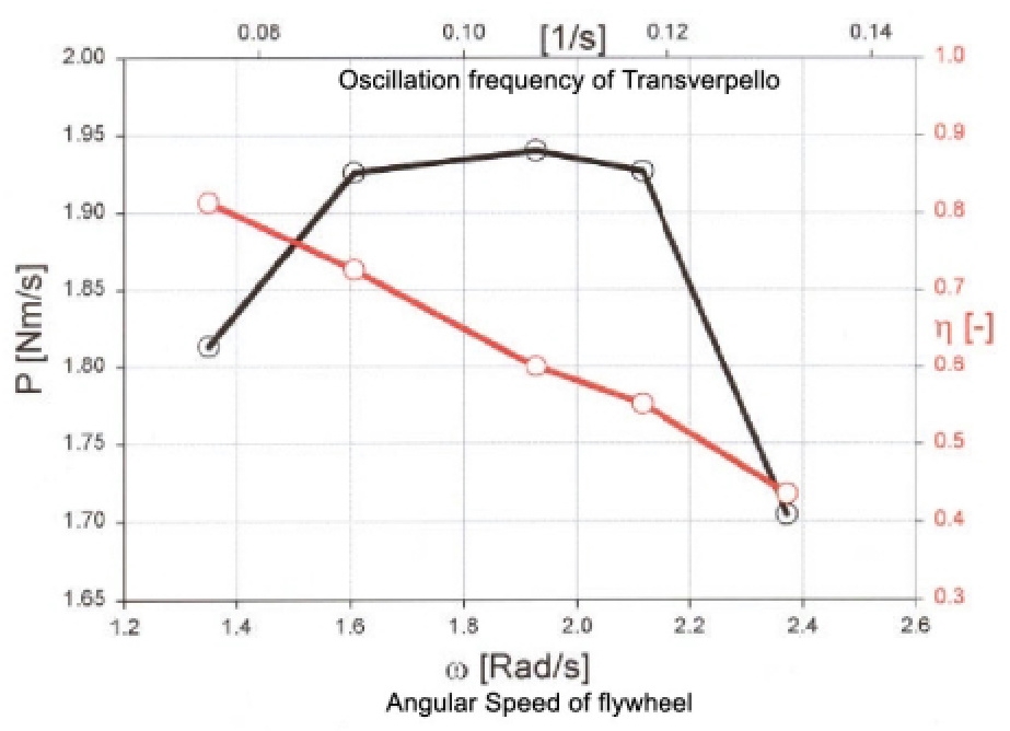
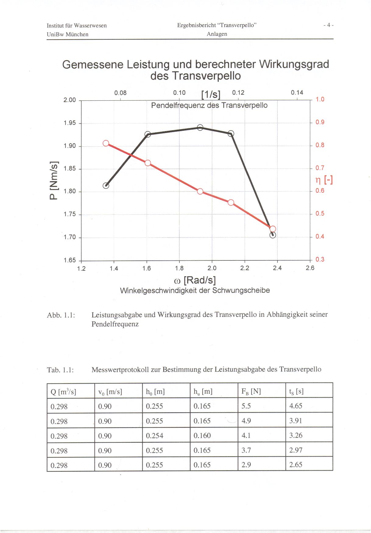
As shown in Figure 1, the power output of the flywheel is
dependent upon on the Transverpello’s oscillation frequency.
This reaches a maximum of 1.94 Nm/s with a frequency of
approximately 0.107 Hz.
The Transverpello’s power is produced by the motion of a
vertically mounted wing section and can therefore be given as
follows. The lift strength FF of the Wing acting in
horizontal direction measures:
FF=AF·CA·ρ/2·v²=h·lF·CA·ρ/2·v² [N]
(AF = Wing area, CA = Lift coefficient,
ρ = Fluid density, v = mean flow rate, h = lift-producing water depth,
lF = Wing depth)
The power produced by the wing is a factor of the lift strength
FF and the frequency of the oscillating motion fF.
The following results:
PF=FF·s·fF=h·lF·CA·ρ/2·v²·s·fF [Nm/s]
|
|
|
The lift coefficient of the wing (1F=1m) is determined
by estimating a relevant mean value along the oscillation route
(s=0.41m) of CA=0.65. The lift-producing water
depth, h corresponds to the average flow depth along the wing profile,
minus the mounting height (hF=4cm) of the wing
above the base of the channel (h=(h0+hu)/2-hF).
The flow velocity at the wing profile is determined from a mean
value of the flow velocity upstream, v0 and downstream,
vu of the Transverpello. The latter is derived from
the continuity relationship as follows: vu=v0·h0/hu.
Using the effective water depth, h, the mean flow velocity, v,
and the oscillation frequency, fF, approximate values
for power output of the wing, PF can be calculated
from which the efficiency η of the Transverpello and its
mechanical components can be estimated.
Using the methods described here one can demonstrate that as
the oscillation frequency increases, the Transverpello’s
efficiency reduces to values between η=0.81 and η=0.44.
This is caused by the increased motion (friction) of the
mechanical components with increased oscillation.
The test series confirms the basic function of the Transverpello,
measures its power output according to oscillation frequency
and estimates approximate efficiency levels.
|
|
Neubiberg, 17th October 2001
|
testing:
|
|
Professor Dr.-Ing. W. Bechteler
|
Dr.-Ing. H. Kulisch
|
|
|
|
|
Appendix:
Measured power output and computed efficiency of the Transverpello
|
|
Figure 1.1:
|
Power output and efficiency of the Transverpello according
to oscillation frequency
|
|
Table 1.1:
|
Measurings taken to determine power output of the Transverpello
|
|
Q [m³/s]
|
v0 [m/s]
|
h0 [m]
|
hu [m]
|
FB [N]
|
ts [s]
|
|
0.298
|
0.90
|
0.255
|
0.165
|
5.5
|
4.65
|
|
0.298
|
0.90
|
2.255
|
0.165
|
4.9
|
3.91
|
|
0.298
|
0.90
|
0.254
|
0.160
|
4.1
|
3.26
|
|
0.298
|
0.90
|
0.255
|
0.165
|
3.7
|
2.97
|
|
0.298
|
0.90
|
0.255
|
0.165
|
2.9
|
2.65
|
|
|
Original Report in German
Annotations to the transfer of the findings of the experiment on a model to the use
The experiment on a model with the readings amid different loads confirmed the function and the calculation for the output. The rate of the wing motion was between 1/13 and 1/6 of the current velocity. For the reality, we want to raise the wing speed to 1/3 of the fluent speed. This is to be maked without getting into the area of noticeably slighter effeciencies. That is only then possible, if the average effective angle position is steeper than in the experiment. A too steep position at the beginning of the motion could result in a tearing off of the current. Therefore the steeper position is to set in only during the motion. For that it needs an adjustment. For the experiment, this would have been too costly. For the use size, it is however very profitably. The designed hydraulics for the power transmission is capable of supplying also this adjustment.
For the transfer of the experiment results to the reality, therefore it doesn´t come up to be restricted to the rules of resemblance. First the changed proportion of the wing motion rate to the fluent speed is to be considered. And secondly the loss of time at the turning point decreases because of the aid of the hydraulics from 30% to 20%.
Output determination
|
Formula out of the findings report (page 2 lower middle):
|
|
F = h * lF * ca * ρ / 2 * v²
|
Side power of the wing [N] |
|
(Joukowski-formula for lift of a wing) |
|
Formula out of the findings report (page 2 bottom):
|
|
P = h * lF * ca * ρ / 2 * v² * s * f |
Output of the wing [Nm/s] |
with it s is the total side way of the wing in [m] (there and back)
and f is the pendulum frequency in [Hz], therefore [1/s]
The product of both values corresponds to the average side speed of the wing in [m/s] considering the delay in the turning point processes.
The geometry of the Transverpello so is designed that the side speed (on average of the actual side motion) corresponds to the 0,35-fold fluent speed of the water.
The losses from the time for the turning point processes are c. 20%.
Instead of s * f does it say thus now: 0.35 * v * (100 - 20) / 100
So it is managed to let out the side way and the frequency and to determine instead of this the average side speed with dependence on the fluent speed.
The total output formula reads then generally:
P = h * lF * ca
* ρ / 2 * v² * v * vs * (100 - WZV) / 100
with it vs is the propose of the side speed to the fluent velocity
and WZV the loss of time at the turning point in [%]
This theoretical output naturally not entirely is obtained how also the findings reports shows.
Yet the mechanical efficiency η is introduced therefore.
Now all values constant for a wing type resp. a building type are summarized to
K = ρ / 2 * ca * η * (100 - WZV) / 100 * vs
If K is determined for a wing type, the finished output formula reads:
Output P = h * lF * v³ * K [W]
| Example |
| Items: |
| Moistened height of the wing h |
2,00 |
m |
| Total length l |
20,00 |
m |
| Side „route” overall |
17,00 |
m |
| Current velocity of the water v |
2 |
m/s |
| Density of the water ρ |
1000 |
kg/m³ |
| CA-Value |
0,69 |
– |
| Mechanical efficiency of the construction η |
0,75 |
– |
| Loss of time at the turning point WZV |
20 |
% |
| Side speed / fluent speed vs |
0,35 |
– |
| Calculations: |
| K = ρ / 2 * ca * η * (100-WZV)/100 * vs = |
72,45 |
kg/m³ |
| Side speed |
0,70 |
m/s |
| Duration one way |
30,36 |
s |
| Duration one period |
60,71 |
s |
| Frequency of the wing |
0,0165 |
Hz |
| Output P = h * l * v³ * K |
23184 |
Nm/s = W |
Confirmation by the Technical University Darmstadt, Germany:
Translation
|
Output calculation of the Transverpello
The output characteristic measured at the University of the Federal Armed Forces Munich on a model and also the progress of the efficiency with dependence on the angular speed [1] express the typical conduct [2], that is inherent in all renewable systems: output maximum in a distinguished angular speed and as of the angular speed falling off efficiency.
Also the projection from the model wing (length 1m, height 0,2m) to an original wing (length 20m, height 2m) can be confirmed. The mean output of about 2 W gaged on the model increases in the original implementation to the order of 20 kW mentioned in the example calculation [3].
|
|
[1]
|
Bechteler/Kulisch: Findings report “Transverpello”, University of the BW Munich, 2001
|
|
[2]
|
Unger: Alternative Energietechnik, Teubner, 1997
|
|
[3]
|
Kroeber/Mühlhaus: Example calculation for the output determination of a Transverpello wing
|
|
Darmstadt, January 28th 2005
Prof. Dr.-Ing. habil. J. Unger
|
|
Original
Lutz Kroeber 2008 Transverpello
|